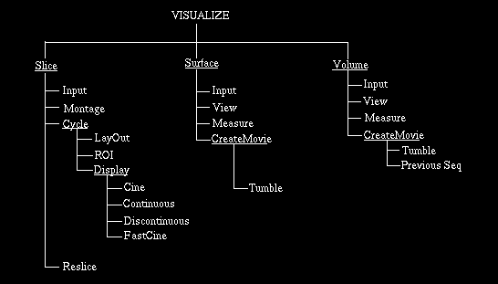
Fig 10.1 Commands Under Visualize.

Fig 10.1 Commands Under Visualize.
10.1 Slice
10.1.1 Summary of Commands
If you have a set of scene and/or display data and if you want to view
them together in some combination, then these are the relevant commands.
Scene data, however, can also be viewed in much restricted ways using
most of the commands under PREPROCESS-SceneOperations and ANALYZE-Scene.
Input allows selecting any number of input files of type IM0, BIM and/or
MV0. Montage allows viewing the input data as a montage and paging
through them. Cycle allows any arbitrary LayOut of the pictures and/or
their selected ROIs and Displaying them in a FastCine fashion
automatically or under mouse control (Continuous and Discontinuous).
Reslice makes it possible to reslice the input data (only scenes) in
arbitrary ways and to view the resulting slices or to output them.
10.1.2 Common Options
LABELS: This is a switch with two states, ON and OFF. In the ON state,
certain descriptors related to the picture such as the data set number,
the indexes of the slice or of the picture, and the scale factor for
magnification are displayed overlaid on the picture. A scale factor of 1
corresponds to 1:1 correspondence between the pixels of the displayed
picture and the input picture (from scene or display data) it
represents. In the OFF state, the labels are removed and the displays
are slightly faster than when the labels are ON. The default state for
LABELS is ON.
INTERP: This also is a switch with two states, ON and OFF. When a slice from an input scene or a picture from an input display data set is displayed, it is usually subjected to scaling. The displayed picture is not a one-to-one mapping of the input picture. This means that in computing the displayed picture, interpolation is needed. When INTERP is ON, the displayed picture is smooth (especially around the edges) since interpolation is done in this case based on the intensities of pixels in a small neighborhood. When INTERP is OFF the interpolated intensity is determined based on the intensity of the nearest pixel and hence the picture is somewhat rough. Smooth interpolation is usually more time consuming, therefore, use the switch with care. No interpolation is done for 8-bit display data of Movie0 type (MV0 files).
The default state for INTERP is OFF.
DATA SET, GREY MAP: DATA SET is a switch with as many states as there are number of input files selected. Suppose we selected 3 input files: one IM0 file, and two MV0 files constituting a surface rendition and a volume rendition of some structure in the scene represented by the IM0 file, each with its own color map. Suppose also that the surface renditions are pseudo-color pictures and volume renditions are true-color pictures. DATA SET then has three states (values): 1, 2, and 3. This switch works in conjunction with the button GREY MAP. When DATA SET has state 1, the grey map applied to the slices of the input scene selected can be changed using GREY MAP (see Section 7.2 for operation of GREY MAP). When DATA SET is in state 2, the GREY MAP button is not applicable to the input pictures since they are of pseudo-color type (hence the GREY MAP button is then removed), but the associated color map is applied to the pictures. This will display the pictures in data set 2 in their correct form; however, this may make pictures displayed from other data sets have a wrong appearance. Similarly, when DATA SET is set to 3, any volume renditions shown from data set 3 will have the correct appearance, but pictures from other data sets may not appear right. Thus DATA SET and GREY MAP can be used in combination to view pictures of any type with this own grey and color maps in an independent fashion. When multiple IM0 files are input, the display of the slices in each IM0 file can be controlled independently using GREY MAP without affecting the display of slices from the other file. If the machine displaying the pictures is of direct color visual class (with 24 bits), all data sets can be displayed in their respective grey/color maps simultaneously.
The default data set number is 1. The default display has the default grey (color) map. The data sets are numbered in the order in which they are selected via Input.
DIMENSION, D.STATUS: These are both switches used for controlling the order of the slice indexes considered in cine display and in display using the buttons PREVIOUS and NEXT. These switches are provided only when the scenes are of dimensionality at least 4. For 4D scenes, the possible states of DIMENSION are 3 and 4. D.STATUS (for dimension status) has two states ON and OFF. The use of these switches is best explained with a 4D example. Consider a dynamic 4D scene with 10 slices for each of 8 time instants. To display the slices in a cine mode in the order of their x_3 indexes for a fixed time instant, say 6, set the x_4 index to 6 using the SET INDEX button, set D.STATUS to OFF when DIMENSION is set to 4, and set D.STATUS to ON when DIMENSION is set to 3. To display the slices in a cine mode in the order of their x_4 indexes for a fixed x_3 index, say 2, set the x_3 index to 2 using SET INDEX, set D.STATUS to ON for DIMENSION 4 and D.STATUS to OFF for DIMENSION 3. When D.STATUS is ON for both DIMENSION 3 and 4, both indexes change with the x_3 index changing more rapidly than the x_4 index.
MEASURE: This option, provided as a button, allows the user to measure cell location, distances and angles by pointing to locations on the pictures displayed. The option is applicable only to scene data.
Upon selection of the option, the mouse button states will be as shown in Figure 10.2. Points for measurement are selected using the cursor and the left button. When the first point is selected on a picture, the coordinates of the cell pointed to in the slice are reported in the dialog window. When the second point is selected, its cell coordinates are reported. Additionally the length (in the 3D space) of the line segment connecting the centers of the two cells is also shown if the cells have the same time coordinate (in case of a dynamic scene). For the third and subsequent points, the measures reported are: the coordinates of the cell pointed to by the most recent point, the length of the line segment connecting the centers of the cells pointed to by the most recent two points, the cumulative length, and the angle between the most recent two line segments. If the point selected is on a slice with different time index from those of the previous points, then the measures reported are: the current cell coordinates, and speed of movement of the current cell (assuming that the previous cell pointed to and the current cell represent the same physical location on the dynamic object). Other measures are reset. To measure speed correctly, it is therefore important to select points in two time instants that represent the same physical point on the object.

Fig 10.2: Mouse Button States for MEASURE.
The middle button can be used to reset the measures to the condition
that existed at the start. This also removes the marks put by the point
selection process. The MEASURE option should be terminated by pressing
the right button before other commands and options can be selected.
10.1.3 Commands
10.1.3.1 Input
This command should be used for selecting the desired IM0 and MV0 files.
If the most recently selected files are appropriate, it is not necessary
to initiate this command. For details of operation, see Section 7.1.
10.1.3.2 Montage
The main purpose of this command is to allow examination of input
pictures in an overall fashion. The panel options available under this
command are listed in Figure 10.3.

Fig 10.3: Options Available Under Montage.
Upon selection of Montage, the mouse button states become as shown in Figure 10.4, and input pictures are displayed in an array as a montage. The number of columns in this array is determined by the current value of the switch COL. The number of rows in the array depends on the total number of pictures in the input files. In each row, the pictures are arranged by the slice indexes in dimension 3 and 4 for scene data and by the picture indexes for display data. In each column, they are arranged by the data set number. Suppose we select two input files, the first containing a 4D scene of domain 256256108 and the second containing 3D display data with 10 pictures. Suppose COL is set to 6 and that the image window can accommodate 4 rows of pictures. Then the pictures are laid out in the montage as illustrated in Figure 10.5. The figure shows the first "page" of the montage. The second page will consist only of data set 1, with the rows (2nd and 4th) corresponding to the second data set shown empty. The indexes are displayed in the upper-left corner of the picture as S: (i_n,....,i_1), where S is the data set number and i_1,....,i_n are the first, second, . . . . indexes. In summary the pictures are displayed in the order of their indexes in each row (slice index for scene data and picture index for display data) with the first index changing most rapidly, the second changing less rapidly than the first, and so on. The successive rows are assigned to the successive data sets.

Fig 10.4: Mouse Button Status for Montage.
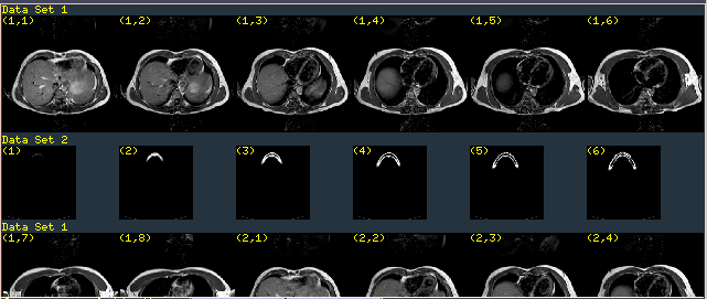
Fig 10.5: Illustration of Montage Display.
The pictures in the montage are displayed such that they are in the correct proportion. Thus, if we display two input scene data sets representing MR scans of the head of two patients whose heads are in a 3:4 ratio, the size of the displayed images will be roughly in that ratio. If the proportionality cannot be maintained meaningfully, then the displayed images will not be in the correct proportion. An example of this situation is if one of the data sets is a set of microscopic images with pixel size of the order of microns and the other set is a tomographic scene with pixel size of the order of a millimeter.
RESET: This option is implemented as a button. When it is selected, it removes any magnified images created using the MAGNIFY option (see below) and resets the switch COL to the default state.
MAGNIFY: The purpose of this option is to select any pictures from the montage and to magnify them arbitrarily. When the option is selected, it puts up its own associated panel options as shown in Figure 10.6, and the mouse buttons are set to state 1 shown in Figure 10.7. This figure illustrates how to proceed to create a magnified image using the mouse and its buttons.

Fig 10.6: Options associated with MAGNIFY.
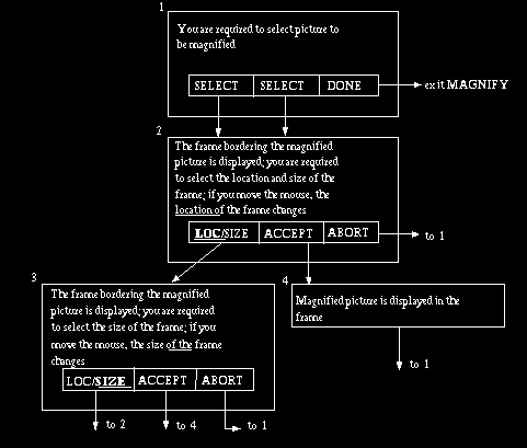
Fig 10.7: Mouse button state diagram for MAGNIFY. An arrow coming out of a
button indicates that that button is clicked. Thus, state 1 to 2 transition
takes place if the left or middle button is pressed in state 1.
The RESET, INTERP, MEASURE, DATA SET, and GREY MAP options associated with MAGNIFY work exactly as these options function elsewhere within Slice (see Section 10.1.2). ERASE allows removing any magnified images. When ZOOM is selected, a scale is set up in the dialog window for selecting a ZOOM factor. This option allows zooming in on any of the magnified images (but not on other pictures). The zoom factor is chosen on the scale. This option should be terminated by pressing the right button before other options can be selected.
MODE: The left and middle mouse buttons (see Figure 10.4) can be used to visualize any part of the montage. If the switch MODE is set to PAGE, the mouse buttons allow getting the next or previous pages of the montage. In the other state of MODE, namely SCRL, the mouse button states will be UP, DOWN, and DONE, and the montage can be scrolled up or down one row at a time using the left and middle buttons. Pressing the right button causes exit from the Montage command. The default setting of MODE is PAGE.
COL: This is a switch whose value determines the number of columns of pictures displayed in the montage. The default is 6.
Other options in MONTAGE - INTERP, MEASURE, DATA SET, and GREY MAP work
as they do elsewhere in the Slice command (see Section 10.1.2).
10.1.3.3 Cycle
Cycle has three commands under it: Layout, ROI, and Display.
Slice-Cycle-Layout
In the Cycle mode of display, two types of pictures are displayed. The first type is called the icon. It is a representation of each input data set by one picture. In the Cycle mode, the display contains as many iconic pictures as there are input data sets. The second type is called the roi pictures. Each roi picture represents an ROI selected from one of the iconic pictures. Layout allows planning the layout of the iconic and roi pictures. The number of roi pictures can be anything. The pictures carry a label, "icon" or "roi", at their lower left depending on their type. The iconic pictures could be reduced to a very small size and set aside at a corner of the image window making room for laying out roi pictures. Alternatively, if roi pictures are not needed and iconic pictures are the main windows for visualizing the input data sets, they can be enlarged to the required size and laid out centrally in the image window. (Layout does not create roi pictures; the ROI command under Cycle should be used for creating roi pictures.)
The operation of Layout is identical to that of the MAGNIFY option described in Section 10.1.3.2, Figure 10.7. The panel options available for Layout are shown in Figure 10.8. They function exactly as in other commands.

Fig 10.8: Panel options for Layout and ROI.
Slice-Cycle-ROI
This command allows selecting ROIs on iconic pictures and laying them out at any magnification anywhere within the image window. In other words, the purpose of this command is to create roi pictures. Its operation is illustrated in Figure 10.9. Note that ROIs can be selected only on iconic pictures and not on roi pictures. The panel options and their description are as for Layout.
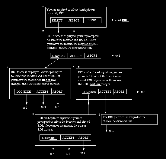
Fig 10.9: Mouse button state diagram for ROI. An arrow coming out of a
button indicates that that button is pressed. For example, state 1 to 2
transition takes place when the left or middle button is pressed while in
state 1.
If you select an ROI and deposit it on an icon, you cannot select an ROI in that area. To remove this effect, select the RESET or ERASE option.
Slice-Cycle-Display
The commands under Display actually make it possible to display the pictures in a dynamic fashion according to the chosen layout. Depending on the mode of display, four commands are available.
Slice-Cycle-Display-Cine: The state diagram associated with this command is shown in Figure 10.10.
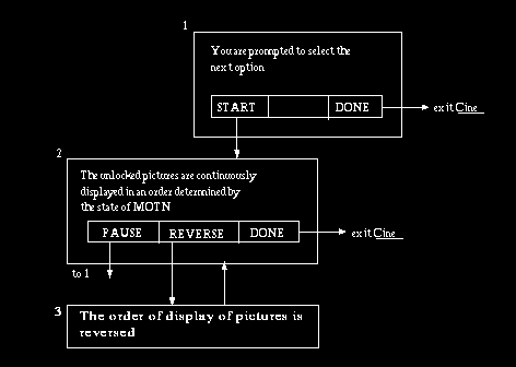
Fig 10.10: Mouse button state diagram for Cine and FastCine. An arrow
coming from a button indicates that that button is pressed. For example,
state 1 to 2 transition takes place when the left button is pressed.
The order in which pictures are displayed in state 2 in Figure 10.10 is determined by the state of the panel switch MOTN. If the middle button (REVERSE) has not been pressed so far, this order is the increasing order of the slice and picture indexes if MOTN is in state 1-WAY. For a 3D scene consisting of 10 slices, this order is: 1, 2, . . . . ,10, 1, 2, . . . . . For a 4D dynamic scene with 10 slices in each of 8 time instants, this order is: (1, 1), (1, 2), . . . . ,(1, 10) (2, 1), (2, 2), . . . . ,(8, 9) (8, 10), (1, 1), (1, 2), . . . . If, in state 2, REVERSE is pressed, this order will be reversed. If the state of MOTN is 2-WAY, the orders without reversal for the above examples are: 1, 2, . . . . ,10, 9, 8, . . . . ,1, 2, . . . . , and (1, 1), (1,2), . . . . ,(1, 10) (2, 1), (2, 2), . . . . ,(8, 9) (8, 10), (8, 9), (8, 8), . . . . ,(8, 1), (7, 10), (7, 9), . . . . ,(1, 2) (1, 1), (1, 2), . . . . REVERSE causes this order to be reversed. Selecting REVERSE two times brings us back to the order we started with.
In both state 1 and state 2 (Figure 10.10), we can select any of the panel options available for Cine, shown in Figure 10.11. Whenever an option is selected, the current operation is interrupted, letting the user complete the selection process associated with the option. When the option is completed, control is returned to the state in which option selection was made.

Fig 10.11: Panel Options for Cine.
INIT INDEX: This option allows resetting each of the slice and picture indexes for current display to 1.
MOTN: This is a switch with two states, 1-WAY and 2-WAY. It is used to control the motion of the pictures chosen for display. 1-WAY causes picture indexes to change in only one direction. 2-WAY causes a to-and-fro change.
The remaining options -- ERASE, INTERP, LABELS, MEASURE, LOCK, UNLOCK, SET INDEX, DATA SET and GREY MAP work exactly as they function elsewhere within the Slice command (see Section 10.1.2).
Slice-Cycle-Display-Continuous: This command operates in a way similar to the Cine command. Its state diagram is shown in Figure 10.12. The main difference between the command and Cine is that the display of successive pictures in this command is controlled by movement of the mouse. Also the REVERSE option is not provided on the mouse button. Instead, mouse movement to the right indicates forward order and to the left indicates reverse order. The speed with which pictures are displayed depends on the mouse speed as determined by the panel button SPEED (see Section 7.2 for a description of its operation) as well as the power of the workstation on which 3DVIEWNIX resides. The panel options available for Continuous are shown in Figure 10.13.
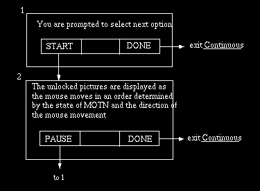
Fig 10.12: Mouse state diagram for Continuous. An arrow coming out from a
button indicates that that button is pressed.

Fig 10.13: Panel options for Continuous and Discontinuous.
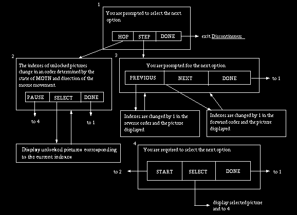
Fig 10.14: Mouse button state diagram for Discontinuous: An arrow leaving
a button indicates that that button is pressed.
INIT INDEX, ERASE, and MOTN work as described under Cine. Other options are described in Section 10.1.2.
Slice-Cycle-Display-Discontinuous: The purpose of this command is to display the picture, not continuously as in Cine and Continuous, but when the user requests. The slice and picture indexes are changed under mouse control and when the desired picture is reached, as indicated by the indexes, it is displayed. The state diagram for this command is shown in Figure 10.14.
The panel options available are as for Continuous (Figure 10.13). Any of the panel options can be selected in any of the states (Figure 10.14) as in Cine and Continuous.
Slice-Cycle-Display-FastCine: This command works exactly like Cine
except that it generally displays pictures more rapidly than Cine. Its
state diagram is shown in Figure 10.10. Its panel options, shown in
Figure 10.15, are a subset of the options in Cine.
In Cine, Continuous, Discontinuous, and FastCine, it is possible to
handle subscenes of input scenes. The subscene is defined in the
SUBSCENE option of the Input command (see Section 7.2). All display
operations are then confined to the subscene only. As an example,
consider a 4D scene of domain 256256108 where the fourth dimension is
time. By setting the first and last index for dimension 3 to 4 and 10,
its increment to 10, the first and last index for dimension 4 to 1 and
8, and its increment to 1, we essentially define a 4D subscene
consisting of only one slice (Slice 4) and all its 8 time instances.
This subscene can be viewed in a cine mode using Cine or FastCine for
visualizing how slice 4 changes over time.

Fig 10.15: Panel options for FastCine.
10.1.3.4 Reslice
The main purpose of this command is to interactively define and create a
rendition of a structure from a given scene (3D or 4D), to specify a
plane of arbitrary orientation, guided by the structure rendition, and
to compute and display cell intensity distribution in the plane. The
command can be used to output a set of such parallel resliced slices as
a scene. If the input is a 3D scene, the plane for reslicing can have
any arbitrary orientation and location. If the input is a 4D scene,
reslicing can be done on any chosen 3D subscene of the 4D scene
corresponding to a fixed value of the x4 coordinate.
As soon as Reslice is selected, a rendition is created of an isosurface resulting from thresholding the input scene at a default value which is 1/3 of the way between the minimum and maximum cell intensity in the scene. The users can change this threshold setting using the panel button THRESHOLD so that an object of their choice is captured in the rendition in some sensible way. For 4D scenes, the first 3D subscene corresponding to the first value of dimension 4 (i.e., the x4 coordinate) is used for defining and displaying the default isosurface. The user can change this index using the panel button SET INDEX (see Section 7.2). The default orientation corresponds to the orientation reached when the object is rotated first about the x-axis and subsequently about the y-axis. The user can change this to any desired orientation using mouse button options.
The rendition also shows a semitransparent plane. The default orientation of the plane is such that it is parallel to the y_1y_2 plane of the structure coordinate system. Its default location is such that it passes through the geometric center of the scene domain. The user can change the location and orientation of the plane in unrestricted ways using the mouse button options.
When the object is rotated, the plane moves with it. In other words, its orientation and location relative to the object orientation remain fixed. When the plane is rotated, the object orientation remains fixed.
The state diagram associated with this command is illustrated in Figure 10.16.
Translation of the plane is controlled by horizontal mouse motion. When the plane is perpendicular to a structure coordinate axis, rightward motion causes the plane to translate along the positive direction of the axis and left-ward motion causes translation along the negative direction of the axis. In other orientations, the direction of motion is best determined interactively.
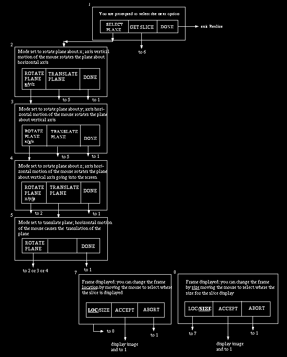
Fig 10.16: Mouse button state diagram for Reslice. An arrow coming out of a
button area indicates that that button has been pressed.
When a plane for reslicing is eventually selected, a frame is displayed indicating the border of the resulting slice. The user can change the location and size of this frame to indicate where and at what size the computed slice should to displayed.
The panel options available under Reslice are listed in Figure 10.17.
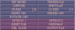
Fig 10.17: Panel Options for Reslice.
THRESHOLD: This option is for selecting the threshold that defines the structure. When this button is selected, two scales are set up, one for specifying the lower end of threshold interval and the other its upper end. The default threshold is min + (max-min)/3 where min and max are the minimum and maximum cell intensities in the input scene.
DIFFUSE, SPECULAR: These are buttons that are used for changing the diffuse and specular reflective properties of the structure displayed. For details of their operation see Section 7.2.
LO RES, HI RES: In the interactive mode, as the object is being rotated, it is rendered at a low resolution in order to give sufficient speed of response to mouse movement so that the user can properly control the orientation of the object. This resolution can be specified by the user via the switch LO RES. The switch values range from 1 to 12, the default value being 4. Lower values correspond to lower resolution. When interactive rotation stops, the object is eventually displayed at a resolution determined by the current value of the switch HI RES whose values also are in the range from 1 to 12. The user can choose the right compromise between display resolution and speed of response using these two switches for the machine on which 3DVIEWNIX resides.
RESET OBJ: This option allows resetting the object orientation to the default orientation. The relationship of the plane to the object is not altered by this action.
RESIZE OBJ: This is a button that allows changing the size of the rendition. When the option is selected, a frame representing the border of the rendition appears. This can be resized by moving the mouse to the left (size decreases) or to the right (size increases). When the desired size is reached, hit the left or middle button to select the new size or the right button to abort the option.
ROTATE OBJ works as described in Section 7.2. Rotation about the z-axis (in the plane of the screen) is controlled by horizontal mouse motion: moving it right-ward causes clockwise rotation and left-ward causes anti-lockwise rotation.
ORTHOG1, ORTHOG2:These options, available as buttons, allow automatically selecting planes that are orthogonal to the x_1 and x_2 axis of the scene coordinate system, respectively. If the input scene is a set of transaxial slices, this means that we can select sagittal and coronal planes. At some orientations of the object, you may not see the selected plane. This will happen if the plane is being viewed edge-on. To overcome this, rotate the object slightly using the ROTATE OBJ option. Since the plane moves with the object, its orientation can now be visualized. Once an orthogonal plane is selected, its location can be changed using the TRANSLATE PLANE option available via the mouse buttons (see Figure 10.16).
RESET PLN: The option, implemented as a button, allows setting the plane to its default location and orientation, that is the center of the scene domain and parallel to the y_1y_2 plane of the structure coordinate system. This does not alter the orientation of the object.
OUTPUT PAR: This option, implemented as a button, is for specifying the parameters of the output scene, if the user intends to create a scene via RESLICE. The mouse button states associated with this option are as in Figure 10.18. The parameters include the first and last location of plane to indicate the extent of the domain of the output scene and the size of the cells in the output scene. In the case of a 3D scene, the cell size to be specified corresponds to the pixel size and slice spacing. For a 4D scene, the cell size corresponds to the pixel size and slice spacing for each 3D subscene of the 4D scene corresponding to each possible value of x4. The output in the latter case is a 4D scene consisting of a resliced 3D subscene for each possible value of x4.
If planes have already been specified for reslicing, in this option, one of them can be selected to indicate the orientation of the plane required to create output slices. To select the current plane, click the left button. To select the plane for which a reslicing operation was previously done, simply place the cursor in the corresponding slice display and click the middle button.
To initiate the actual output operation, select the SAVE option in the output section of the mouse window after changing the output file name if needed. The output will be created as per the most recently specified set of parameters.
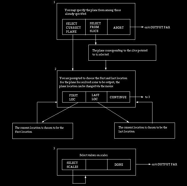
Fig 10.18: State diagram for OUTPUT PAR. An arrow leaving a button
indicates that that button has been pressed.
10.2 SURFACE
10.2.1 Summary of Commands
These commands are for visualizing structures, structure systems and
structure plans in the surface mode via surface rendering. Structures,
however, can also be visualized via surface rendering in a restricted
way using the Reslice command under VISUALIZE-Slice and in less
restricted ways using the commands under MANIPULATE.
Input allows selecting input files of type BS1 each containing a
structure, a structure system, or a structure plan. View provides a
variety of options for visualizing the input structures in their natural
form -- static or dynamic -- and in any combination of the component
structures. Measure is for measuring linear and curvilinear distances
and angles or how these entities change for dynamic structures. Create
Movie allows generating and saving on a file of type MV0 any desired
sequence of views of the input structures which may result from their
natural motion or from user rotation.
10.2.2 Common Options
STR SYS: This is a switch with as many states as the number of input
files that have been selected. In other words, the number of values
taken by this switch is the number of structure systems input. The
switch is used for selecting the structure system for which the chosen
commands are to be applied. The numbers associated with the structure
systems are in the order in which the input files storing them are
selected.
The default value of the switch is 1.
LAYOUT: This is a button whose purpose is to allow the user to change the layout of the renditions of the input structure systems on the screen. The mouse button states associated with this option are illustrated in Figure 10.19. When the option is selected, the frame of the rendition of the current structure system becomes free to be relocated and resized as in states 1 and 2. When a modified frame is eventually accepted, the rendition is displayed.
LEVEL, P.STAT: These are both switches which together allow any of the elements of the parameter vector (other than object number) to be held fixed (P. STAT in OFF state) so that the structure in the current structure system can be displayed in various dynamic modes. Refer to the definition of structure system and parameter vector in Section 3 and the example given there before proceeding. These switches together with buttons SET PARAM and CINE allow us to set up and examine various aspects of the natural dynamics of the current structure system under commands View, Measure, and CreateMovie.
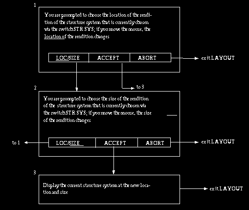
Fig 10.19: The mouse button states associated with LAYOUT.
In order to allow different orders of accessing structures and displaying them, we impose a certain order on the structures contained in a structure system. The order is determined by a tree that we associate with the structure system. The parameters that we allow in 3DVIEWNIX currently are: object number, time instant (for dynamic objects), longitudinal instant, modality and another category called "other". When all of these categories are present in a given structure system, the order of the levels of the tree are assumed to be other, modality, longitudinal time, time instant, and object number. To make these statements clear, consider the example of Section 3 (given under Parameter Vector). The tree representation of the structure system in that example is as follows. When some of the parameters are absent, the order indicated above is still followed, as is clear from the above example.
When structure plan is an input, the order is again determined by the tree associated with the structure plan (see for details).

LEVEL allows us to choose a particular level of the tree (parameter), say modality. P.STAT allows us to set the status of the parameter indicated by LEVEL to ON or OFF. When LEVEL indicates modality, for example, if we set P.STAT to OFF, that means that we cannot change the modality for the objects that are currently chosen while displaying the structure system in a dynamic mode using CINE. The actual values of the parameters for the currently chosen objects are set via the button SET PARAM. Suppose, in the example in Section 3, we wish to display heart muscle (object #1) and blood pool (object #2) with their dynamics for MR (modality #1). Then, we turn off objects 3 and 4 (liver and isodose surface) using switches OBJECT and STATUS, set P.STAT to OFF when LEVEL indicates modality and P.STAT to ON when LEVEL indicates time, and use SET PARAM (see below) to set value on the scale labelled LEVEL 2 to 1 (this means CINE will start at the first time instant) and on the scale labelled LEVEL 1 to 1 (meaning modality is fixed but set to MR and neither to PET nor to the third modality). If, at this point, we select CINE, the heart muscle and blood pool as determined via MR scenes will be displayed in a dynamic mode at a speed determined by the power of the machine on which 3DVIEWNIX resides. The dynamic display is created by rendering structures in the following order of their parameter vectors: [(1, 1, 1), (2, 1, 1)], [(1, 2, 1), (2, 2, 1)], [(1, 3, 1), (2, 3, 1)]. The two structures whose parameter vectors appear within the square brackets constitute object #1 and object #2 at the same time instant. To view the structures in a static mode, P.STAT should be set to OFF when LEVEL indicates time instant. When multiple parameters are ON, say corresponding to time and modality in the above example, the objects are displayed in a certain fixed order as described under CINE below.
The possible states of LEVEL are: 1,, 2, 3, 4, and 5. The actual number of states depends on the parameters represented by the structure system. The default setting of P.STAT is OFF for all parameters.
SET PARAM: This is a button whose purpose is to allow selecting a particular structure in the current structure system by specifying the parameter values associated with the structure. When this option is selected, one scale is set up for each of the parameters used in the current structure system except for the parameter corresponding to object. The values of the parameters are chosen on the scales. In the example given above (under LEVEL, P.STAT), two scales are set up called LEVEL 1 and LEVEL 2, corresponding to modality and time instant, respectively.
The default value of all parameters is 1.
CINE: This option, implemented as a button, allows the actual dynamic display of the structure in an order determined by LEVEL and P.STAT. When this option is selected, a new sub-panel is created with the options shown in Figure 10.20. The mouse button states are exactly as for Slice-Cyc1e-Display-Cine shown in Figure 10.10.
LABELS is a switch with two states, ON and OFF. In the ON state, the parameter values associated with the structures currently rendered are shown at the upper-left corner of the rendition, just like slice indexes are shown in the commands under Slice. In fact the CINE option and the associated options shown in Figure 10.20 are analogous to the Cine command under Slice and its associated options. SET PARAM is analogous to SET INDEX. MOTN, a switch indicating motion with two states 1-WAY and 2-WAY, allows display of the structures in the forward order (see below) (1-WAY) and to-and-fro (2-WAY). D.MODE is a switch with two states ICON and FULL and determines the display mode. When its state is ICON, only the icon is rendered. In the FULL mode, only the full-resolution rendition is displayed.

Fig 10.20: Panel options associated with CINE.
The forward order for the structures is best described using the example considered previously under LEVEL and P.STAT. If we display with object #1 and #2 ON and the rest OFF, with P.STAT set to ON only when LEVEL is set to 2, the forward order of the structures is: [(1, 1, 1), (2, 1, 1)], [(1, 2, 1), (2, 2, 1)], [(1, 3, 1), (2, 3, 1)], [(1, 1, 1), (2, 1, 1)], . . . . when MOTN is set to 1-WAY. If MOTN is set to 2-WAY, the order becomes: [(1, 1, 1), (2, 1, 1)], [(1, 2, 1), (2, 2, 1)], [(1, 3, 1), (2, 3, 1)], [(1, 2, 1), (2, 2, 1)], . . . . When REVERSE mouse button option is selected, the order will be reversed in the two cases. For some settings of LEVEL, the reverse order may not be sensible. For example, when it is set to 2 in the heart example given above, we will essentially see a backward beating heart!
PREVIOUS and NEXT are buttons which allow us to choose previous and next structure for rendition in the order described above. Note that the effect of PREVIOUS in the forward order is the same as that of NEXT in the reverse order.
Obviously, when all states of LEVEL are set to OFF in P.STAT, CINE will not show any dynamics.
MAGNIFY: This is a button which allows changing the magnification of the objects of the currently selected structure system within the frame chosen for the display of its rendition. When this option is selected, a scale is set up to specify the magnification factor. A value of 1 on this scale corresponds to a display of the structure system in life size. Some parts of the structure system may fall outside the frame of the rendition for certain magnification factors. These parts are not displayed.
The default value is set up so as to give an image of reasonable size that captures all aspects of the structure system. If the object is large, it may not be possible to capture within the screen its full rendition. For fast interactive display, the users should select a low magnification value. The optimal value that gives sufficient speed as well as size of rendition depends upon the power of the machine running 3DVIEWNIX.
LIGHT: This is a switch with states 1, 2, 3, 4, and 5. The states allow changing the direction of the illuminating light source that is assumed in creating the renditions, as indicated below.
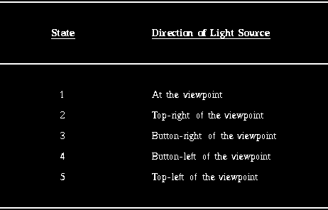
The default setting of this switch is in state 1. As for other options, the optimal setting should be determined experimentally by the user depending on their application and in conjunction with other options.
BOX: This is a switch with two states ON and OFF. When the state is ON, a wire-frame box indicating the domain of the structure system and enclosing the structure system is displayed in the rendition. This may serve to enhance the three-dimensional appearance of the rendered structures. It also serves to show the orientation of the coordinate system associated with the structures.
The default state of this switch is OFF.
10.2.3 Commands
10.2.3.1 Input
This command should be used for selecting the desired BS1 files
containing the structures, structure systems, or structure plans to be
visualized. If the most recently selected files are appropriate, it is
not necessary to initiate this command. Any number of files can be input
simultaneously for visualization. For details of operation of Input, see
Section 7.1.
10.2.3.2 View
The main purpose of this command is to allow visual examination of
object information contained in the current input files. The panel
options available under this command are shown in Figure 10.21
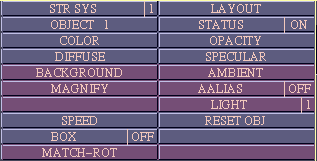 (a)
(a)
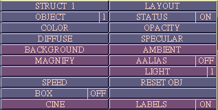 (b)
(b)
Fig 10.21: Panel options for Surface-View. (a) When the number of elements
in the parameter vector of input structures is 1, (b) When this number
is greater than 1.
Upon selection of View, a rendition is created using default rendering parameters for the structures in each of the input files and displayed at a default layout. The layout can be subsequently changed using the panel option LAYOUT. Rendering parameters can be changed using the options COLOR, OPACITY, DIFFUSE, SPECULAR, BACKGROUND, AMBIENT, MAGNIFY, A-ALIAS and LIGHT. The mouse button states associated with this command are illustrated in Figure 10.22.
A particular structure system on which further operations are to be performed is selected by simply moving the cursor on to its rendition and pressing the middle button in state 1. A specific object in this structure system is selected in an analogous fashion by pointing and clicking. These selections can also be made via the panel switches STR SYS, OBJECT and STATUS as described the Sections 10.2.2 and 7.2. When an object is selected by pointing and clicking, its STATUS is set to ON, automatically. These now become the current structure system and object and any object-specific options -- COLOR, OPACITY, DIFFUSE, SPECULAR -- can be applied to them.
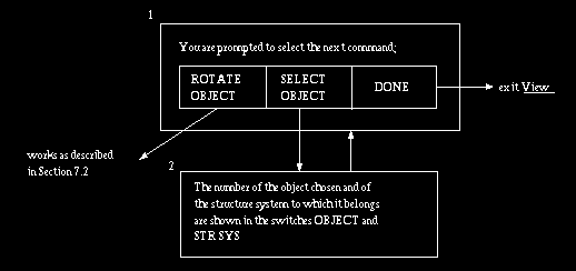
Fig 10.22: State diagram for Surface-View. An arrow coming out of a mouse
button indicates that that button has been pressed.
COLOR, OPACITY, DIFFUSE, SPECULAR, BACKGROUND, AMBIENT, and SPEED operate as described in Section 7.2. STR SYS, LAYOUT, MAGNIFY, LIGHT, and BOX operate as described in Section 10.2.2.
When the structures in a structure system have more than one parameter associated with them, a particular structure to be viewed and the mode of viewing the structure are selected via the options LEVEL, P.STAT, SET PARAM, and CINE as described in Section 10.2.2
RESET OBJ: This option, available as a button, resets orientation of the
current structure system to its unrotated position.
10.2.3.3 Measure
The main purpose of this command is to make it possible to point and
measure linear, curvilinear and angular measures, irrespective of
whether the input structure systems constitute static, dynamic, rigid or
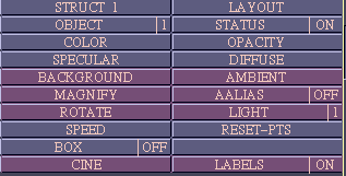
non-rigid objects. The panel options available under this command are
shown in Figure 10.23.
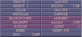 (a)
(a)
 (b)
(b)
Fig 10.23: Panel options for Surface-Measure. (a) When the number of
elements in the parameter vector of input structures is 1, (b) When this
number is greater than 1.
If the View command has previously been selected, the display and layout arrived at in that command are left intact for continuation in Measure. Otherwise, a proper layout of the renditions with appropriate rendition parameters should be created by selecting relevant panel options in Measure. The state diagram associated with this command is illustrated in Figure 10.24.
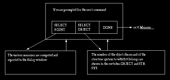
Fig 10.24: State diagram for Surface-Measure. An arrow coming out of a
mouse button indicates that that button has been pressed.
By pointing to a location on a surface in the rendition, the user essentially specifies a point in the view space whose x, y, z coordinates can be calculated. By specifying a series of points in this fashion, a variety of measurements can be made. For static objects, the measures computed and reported in the dialog window are: total length of line segments connecting the successive points specified on the surfaces, the length of the most recent line segment, and the angle between the most recent two line segments. For dynamic objects, additionally, speed is also reported for the most recent pair of points. For the speed reported to be sensible, these two points should constitute manifestations of the same point at two different time instants of the structure. Whenever the user selects a point on a structure at a time instant different from that for which the previous point was specified, speed is reported.
RESET: This panel option removes the overlay display that indicates points and lines connecting the points, and resets all measures so that the measuring process can be started afresh.
All other panel options are as described in Sections 10.2.2 and 7.2.
10.2.3.4 CreateMovie
The main purpose of this command is to create and save in a file a
sequence of renditions depicting continuous rotations, as a single
assembly of the objects in a selected input structure system or plan. If
the input structure system represents dynamic objects, the renditions
may depict just the motion of the objects or this motion together with
rotations of the whole assembly. By creating the structure system or
plan appropriately, a variety of other phenomena can also be captured in
the renditions. For example the different structures may constitute
various iso-surfaces corresponding to a sequence of thresholds specified
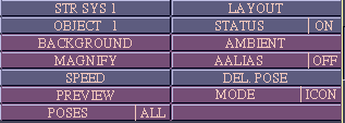
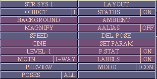
for a 3D or 4D scene. The panel options available for this command and
the state diagram are shown in Figures 10.25 and 10.26, respectively.
 (a)
(a)
 (b)
(b)
Fig 10.25: Panel options for Surface-CreateMovie (a) when the number of
elements in the parameter vector of input structures is 1, (b) when this
number is greater than 1.
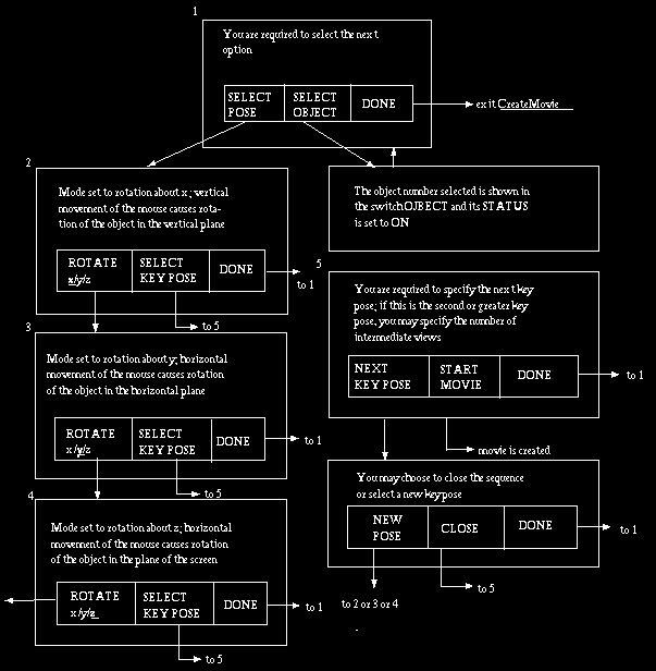
Fig 10.26: Mouse button state diagram for Surface-CreateMovie. An arrow
coming out of a button area indicates that that button has been pressed.
In order to create a sequence of renditions, the user has to specify a set of key poses of the structures. The number of intermediate views to be generated for every pair of key poses should also be specified by the user on a scale called INTERMEDIATE VIEWS. The time to specify this number is after selecting a key pose (in state 5 in Figure 10.26). 3DVIEWNIX generates the specified number of intermediate views by gradually changing the orientation from the first key pose in the pair to the second. A closed (cyclic) sequence can be generated by making the next key pose to be the very first key pose specified. This can be achieved by using the CLOSE option in state 6. Of course, one may continue specifying further key poses after closure, and there may be any number of closed loops of this form in the final sequence specified. The actual generation of the movie sequence starts when the START MOVIE option is selected in state 5. At that time the MAGNIFY option is disabled until the movie is saved.
Obviously, any rotation sequence can be specified using the above mechanism of key poses. As a simple example, consider how a complete 360 movie sequence for rotation about the x-axis starting from some initial orientation of a static object assembly may be specified. We choose the starting position to be the first key pose. Then rotate the objects around x-axis by 120 and select the resulting orientation to be the second key pose. Rotate the object further by 120 and select the third key pose. Subsequently close the sequence by selecting CLOSE.
It is also possible to consider parameters other than object number in creating a movie. For this, we need to select key poses using the appropriate combination of options LEVEL, P.STAT, SET PARAM, and CINE. Consider again the example given in Section 10.2.2 under the description of these options. Suppose we wish to create two movies of the dynamic heart muscle (object #1) and blood pool (object #2) as derived from MR, first without rotations, showing only motion, and then combining both rotation and motion.
For the first situation, first set LEVEL to 2 and P.STAT to ON and subsequently LEVEL to 1 and P.STAT to OFF. This ensures that we capture change due to time and not due to modality. Turn on objects 1 and 2 and turn off objects 3 and 4 (liver and isodose surface). Then select an appropriate orientation for the two objects, set LEVEL 1 and 2 scales both to 1 via SET PARAM, and select this as the first key pose. Without further rotations, select the second key pose also at the same orientation but with LEVEL 2 scale set at 3 and specify the number of intermediate views to be 1. Then select the CLOSE option (see Figure 10.26) and specify the number of intermediate views to be 1. This completes the specification of the key poses, and so select START MOVIE. A movie consisting of four renditions corresponding to time instants 1 ,2, 3, 2 will be created in that order which essentially represents a periodic motion of heart muscle and blood pool if the renditions are displayed repeatedly in the order rendition 1, rendition 2, rendition 3, rendition 4, rendition 1, rendition 2, . . . . . .
For the second situation, proceed as above, but rotate the objects for the second and subsequent key poses to reach the desired orientation and select as many key poses as needed. It is not necessary to set the time instant for the second and subsequent key poses, but set the desired time instant for the initial key pose. For each pair of key poses specify the desired number of intermediate views. A movie is automatically created by mixing rotation and motion due to dynamics. Suppose, in the example under consideration, the starting time instant (for the initial key pose) is 2, and we specify two additional key poses and eventually select CLOSE. Suppose also that the number of views specified for the three pairs of key poses are respectively 3, 2, and 1. Then the movie will have 9 renditions altogether. The renditions of intermediate views depict gradual change of both orientation and time instant. If the key poses are all specified by rotation about a fixed axis, say x, by a rotation of 120 between key poses, then the 9 renditions will have the following (rotation, time instant) pair (here rotations are expressed relative to the initial key pose): (0, 2), (30, 3), (60, 1), (90, 2), (120, 3), (160, 1), (200, 2), (240, 3), (300, 1).
It is also possible to have more than one active parameter. In the above example, it is possible to turn ON both time and modality. The movie then captures changes due to both parameters. The parameter values are changed cyclically as for time instant in the above example. The order of changing of values is: time (most rapidly), modality (next), longitudinal time (next), other (least rapidly). In the example under consideration, if both LEVEL 1 and LEVEL 2 have P.STAT ON, then the 9 renditions will have the following (rotation, time, modality) triple: (0, 2, 1), (30 3, 1), (60, 1, 2), (90, 2, 2), (120, 3, 2), (160, 1, 1), (200, 2, 1), (240, 3, 1), (300, 1, 2).
Obviously, considering the fact that parameter "other" can be defined to be anything the user chooses, a large variety of animations depicting various aspects of changes of object properties can be created.
The panel options for this command are described below.
DEL POSE: This option, available as a button, allows deleting the most recently specified key pose. The option may be selected in states 5 or 6 of Figure 10.27.
PREVIEW: This option, implemented as a button, is for getting a preview of the movie that is to be created for the sequence of key poses that has been specified. The associated state diagram is shown in Figure 10.27. In states 2 and 3, "next frame" is determined by the state of the panel switches D.MODE and POSES.
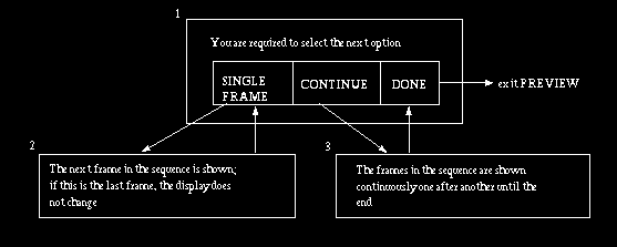
Fig 10.27: State diagram for panel option PREVIEW in Surface-CreateMovie.
An arrow coming out of a button area indicates that that button has been
pressed.
D.MODE: This is a switch with two states ICON and FULL, ICON being the default. When the state is ICON, only renditions of the icon are shown in the PREVIEW option. When the state is FULL, only the full resolution renditions are shown in PREVIEW.
POSES: This is a switch with two states, KEY and ALL, KEY being the default state. When the state is KEY, only the key poses selected are shown in PREVIEW. In state ALL, all poses, including the intermediate ones, are shown in PREVIEW. The four possible combinations of the states of D.MODE and POSES can be used to create a desired mode for PREVIEW.
The switches D.MODE and POSES apply only to PREVIEW. While actually
creating the movie, always the views corresponding to ALL poses and FULL
resolution are generated.
10.3 Volume
10.3.1 Summary of Commands
These commands are for visualizing objects in the volume mode via volume
rendering.
Input allows selecting an input file of type SH0 containing a nonbinary
shell. View provides a variety of options for visualizing the object
contained in the SH0 file. Measure is for measuring linear and
curvilinear distances and angles by pointing to locations on the fuzzily
defined object. CreateMovie allows generating and saving on a file of
type MV0 any desired sequence of views of the input object resulting
from their rotations.
10.3.2 Common Options
MATERL: This is a switch with four states. In medical applications,
possible material types are bone, soft tissue, and fat. Depending on the
actual application and the classification method used, these may
represent other entities even in medical imaging. For example, these may
constitute grey matter, white matter, and cerebrospinal fluid. This
switch is used for selecting a particular material whose color and
opacity are to be changed via the options COLOR and OPACITY (see Section
7.2), or selecting SURF to change the color of the surfaces representing
material interfaces.. (All surfaces have the same color, which is
independent of the material; however, the opacity of a surface is
determined by the opacity of the material behind it if opacity values
are not stored in the input file.)
The states are assigned values SURF, 1, 2, . . . . . , the default state being SURF.
SRF STRNTH: This option, available as a button, allows selecting the degree or strength of depiction of surfaces rather than of materials. It affects only renditions of shells created by Classify-1Feature.
MAGNIFY: This is a button which allows changing the magnification of the structure that is rendered. When this option is selected, a scale is set up to specify the magnification factor. A value of 1 on this scale corresponds to a display of the structures in life size. Some part of the display may fall outside the screen at certain magnification values. These can be brought within the screen using the SCROLL option.
The default value is set up so as to give an image of reasonable size that captures all aspects of the structure. For fast interactive display, the users should select a low magnification value. The optimal value that gives sufficient speed as well as size of rendition depends on the power of the machine running 3DVIEWNIX.
FADE: This is a switch with two states, ON and OFF. In the ON state, smooth renditions of low-opacity objects are created by making use of opacity and color values of voxels in a small neighborhood while computing the color value to be assigned to a pixel in the rendition. This option is computationally slower in the ON state than in the OFF state. Therefore, the user should experimentally determine whether or not to turn this switch ON depending on the power of their machine and on their interactive needs.
SCROLL: This is a button which allows scrolling the rendition within the image window using mouse movement. Its state diagram is shown in Figure 10.28. This option should be terminated by pressing the right button before other options can be selected.
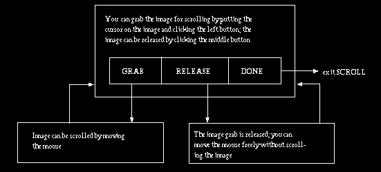
Fig 10.28: Mouse button states associated with SCROLL. An arrow coming out
of a button indicates that that button has been pressed.
BOX: This is a switch with two states, ON and OFF. When the state is ON,
a wire-frame box indicating the domain of the structure and enclosing
the structure is displayed in the rendition. It serves to show the
orientation of the coordinate system associated with the structure
relative to the view space coordinate system.
10.3.3 Commands
10.3.3.1 Input
This command should be used for selecting the desired SH0 file
containing the object to be visualized. If the most recently selected
file is appropriate as input, it is not necessary to initiate this
command. At present, only one input file is permitted. All structure
information that is to be visualized should be captured in one shell in
the input SH0 file. That is, the structure system to be visualized in
the volume mode should have only one structure, and hence only one
object.
10.3.3.2 View
The main purpose of this command is to allow visual examination of the
structure contained in the current input file. Upon selection of View, a
rendition is created of both an icon -- a coarse representation of the
structure -- and of the full resolution structure using default
rendering parameter values. These values can be subsequently changed
using the various panel options. The state diagram associated with this
command is essentially that of the ROTATE OBJECT option (Section 7.2)
and is shown in Figure 10.29. Rotation is always assisted by an icon for
convenient real-time interaction for reaching the desired orientation.
When the icon rotation stops, the full resolution rendition appears.
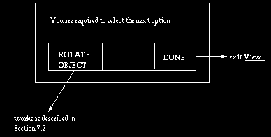
Fig 10.29: State diagram for Volume-View.
The panel options available for this command are shown in Figure 10.30.
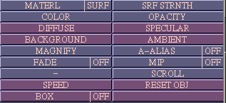
Fig 10.30: Panel options for Volume-View.
RESET OBJ: This option, available as a button, resets orientation of the structure to its unrotated initial orientation.
Shell data created by Classify-2Features do not include information on different materials; therefore, settings for material 1, 2, and 3 have no effect on renditions of these objects.
COLOR, OPACITY, DIFFUSE, SPECULAR, BACKGROUND, AMBIENT, A-ALIAS and SPEED operate as described in Section 7.2. Other options are described in Section 10.3.2.
When non-achromatic colors are chosen for the various materials via the
COLOR option, View generates true-color renditions. If the display
device is of the pseudo-color visual class, strange color changes of the
various windows may take place. This is because 3DVIEWNIX attempts to do
a best approximation of the true-color picture by a pseudo-color
picture. If you do not like the result, change material colors back to
grey. For accurate portrayal of the detailed renditions created by View,
the pictures should be displayed on a device of direct-color visual
class.
10.3.3.3 Measure
The main purpose of this command is to make it possible to point and
measure linear and curvilinear distances and angles on the input fuzzy
structure.
If the View command has previously been selected, the display arrived at in that command is left intact for continuation in Measure. Otherwise, a proper rendition with appropriate rendering parameters should be first created by selecting relevant panel options in Measure (see Figure 10.31). The state diagram associated with this command is illustrated in Figure 10.32.
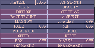
Fig 10.31: Panel options for Volume-Measure.
By pointing to a location in the rendition, the user essentially points to a location on the fuzzy structure which is taken to be the most likely boundary point along that line of sight. The likelihood of a boundary point is determined by the gradient magnitude at the point of the scene from which the fuzzy structure was derived. The measures computed and reported in the dialog window are: total length of line segments connecting the successive points specified on the structure, the length of the most recent line segment, and the angle between the most recent two line segments.
The panel options for Measure are as follows (see Figure 10.31).
RESET: This option, a button, removes the overlay display that indicates points and lines connecting the points, and resets all measures so that the measuring process can be started afresh.
MARKS: This is a switch with two states, ON and OFF. In its ON state, the option SET MARKS can be used to lay marks on the structure boundary. It also displays any previously laid marks in that state. These marks can be used as artificial land marks for the measurement process.
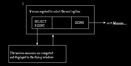
Fig 10.32: State diagram for Volume-Measure. An arrow leaving a button
indicates that that button has been clicked.
SET MARKS: This is a button that allows setting marks on the structure. When this option is selected, it turns MARKS to the ON state and proceeds as indicated in the state diagram of Figure 10.33.
The marks become a part of the structure and they will appear in the correct location even if the structure is rotated, magnified, scrolled, etc. They can be removed using the ERASE MARKS option.
ERASE MARKS: This is a button which when selected turns MARKS to the ON state and proceeds exactly as the SET MARKS option, except that it allows erasing previously laid marks. The state diagram is shown in Figure 10.34.
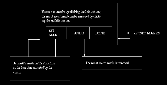
Fig 10.33: State diagram for the SET MARKS option in Volume-Measure.
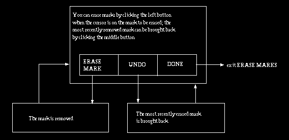
Fig 10.34: State diagram for the ERASE MARKS options in Volume-Measure.
All other panel options for Measure are as described in Sections 10.3.2
and 7.2.
10.3.3.4 CreateMovie
The main purpose of these commands is to create and save in a file a
sequence of renditions depicting continuous rotations of the input
structure.
There are two commands available for creating movies: Tumble and PrevSeq. Tumble works in a fashion analogous to Surface-CreateMovie. PrevSeq allows creating movies for previously specified sequences of views.
CreateMovie-Tumble
The state diagram for this command is shown in Figure 10.35. In order to create a sequence of renditions, the user has to specify a set of key poses of the structure. The number of intermediate views to be generated for every pair of key poses should also be specified by the user on a scale called INTERMEDIATE VIEWS. The time to specify this number is after selecting a key pose (in state 5 in Figure 10.35). 3DVIEWNIX generates the specified number of intermediate views by gradually changing the orientation from the first key pose in the pair to the second. A closed (cyclic) sequence can be generated by making the next key pose to be the very first key pose specified. This can be achieved using the CLOSE option in state 6. Of course, one may continue specifying further key poses after closure and there may be any number of closed loops of this form in the final sequence specified. The actual generation of the movie sequence starts when the START MOVIE option is selected in state 5. At that time, the MAGNIFY option is disabled until the movie is saved. Since the structure system allowed as input should contain only one structure, this command cannot create movies that capture dynamics and other object properties in its present form, as VISUALIZE-Surface-CreateMovie can. At present, the movie must be created in the foreground mode; therefore the RUN-MODE switch in the mouse window is not displayed.
Obviously, any rotation sequence can be specified using the above mechanism of key poses. As a simple example, consider how a complete 360 movie sequence can be specified for rotation about the x-axis starting from some initial orientation of the structure. We choose the starting orientation to be the first key pose. Then rotate the object around x-axis by 120 and select the resulting orientation to be the second key pose. Then rotate the object around the x-axis again by 120 and select the resulting orientation to be the third key pose. Subsequently, close the sequence by selecting CLOSE.
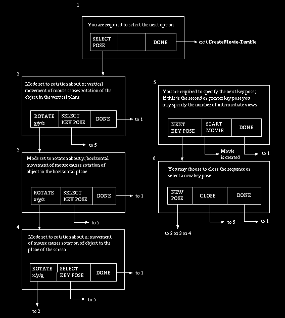
Fig 10.35: State diagram for Volume-CreateMovie-Tumble. An arrow leaving a
mouse button indicates that that button has been pressed.
The panel options available for this command are shown in Figure 10.36 and are described below.
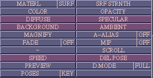
Fig 10.36: Panel options for Volume-CreateMovie-Tumble.
DEL.POSE: This option, available as a button, allows deleting the most recently specified key pose. The option may be selected in states 5 or 6 of Figure 10.35.
PREVIEW: This option, implemented as a button, is for getting a preview of the movie that is to be created for the sequence of key poses that has been specified. The associated state diagram is shown in Figure 10.37. In states 2 and 3, "next frame" is determined by the state of the panel switch MODE and POSES.
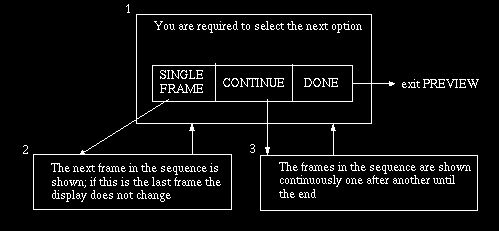
Fig 10.37: State diagram for panel option PREVIEW in
Volume-CreateMovie-Tumble. An arrow leaving a mouse button indicates
that that button has been clicked.
D.MODE: This is a switch with two states ICON and FULL, ICON being the default. When the state is ICON, only renditions of the ICON are shown in the PREVIEW option. When the state is FULL, only the full resolution renditions are shown in PREVIEW.
POSES: This is a switch with two states, KEY and ALL, KEY being the default state. When the state is KEY, only the key poses selected are shown in PREVIEW. In state ALL, all poses, including the intermediate ones, are shown in PREVIEW. The four possible combinations of the states of D.MODE and POSES can be used to create a desired mode for PREVIEW.
The states D.MODE and POSES apply only to PREVIEW. While actually creating the movie, always the views corresponding to ALL poses and FULL resolution are generated.
CreateMovie-PreviousSeq
The purpose of this command is to make it possible to create a movie for the most recently specified sequence of key poses. This specification need not be in the current session of 3DVIEWNIX. The idea here is that when repeated types of 3D imaging operations are done on a large number of data sets, user time can be saved by allowing a one-time specification of a movie protocol. Movies can then be generated automatically for the different data sets. If no key pose sequence has previously been specified, this command will complain so and will not create a movie.
To create a movie, simply select the SAVE option for OUTPUT in the mouse window. The panel options available in this command are shown in Figure 10.38. These options have already been described in Sections 10.3.2 and 7.2. If you do not select SAVE, subsequent sequences will be appended to the same movie until you exit the CreateMovie command, when the movie will be saved.
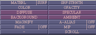
Fig 10.38: Panel options for Volume-CreateMovie-PreviousSeq.
 User Manual
 Library Ref. Manual
 Tutorial
